

Sign In Join Free


1 / 5
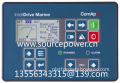
ComAp InteliDrive Marine ID2C2004BAA Engine controller for Marine Applications


Basic Info
| Brand Name | ComAp |
|---|
Product description
Engine controller for marine Tier4 Final propulsion applications
Control, monitoring and protection for any type of marine engine
Support of EFI (ECU) engines via CAN/J1939 or Cummins Modbus
Redundant architecture by using backup redundant protection unit Inteli RPU
Support of two independent power supplies via I-RPU module
7 configurable binary inputs, 7 configurable binary outputs
9 configurable analogue inputs (3 resistive, 3 current 0-20mA, 3 voltage 0-10V)
Option for additional inputs/outputs
Selectable protections warning/cooling down/shutdown
3 level of controller setting / operation password protection
Ethernet, USB, GSM / GPRS, RS485 or RS232 / Modem / Modbus communication
Automatic SMS on alarm
On-line control and monitoring over web pages (embedded web server)
Real time clock and event history log
Toggle button with additional features adjustments
Up/Down speed regulation buttons on the front facia
2 languages (user changeable), Chinese language support
Front panel sealed to IP65
Modular engine controller designed for diesel driven fire pump applications based on the NFPA 20 standard
Automatic and manual starting sequence based on two batteries according to NFPA 20 standard
Support of engines equipped with Electronic Control Unit (ECU) - J1939 or Cummins Modbus interface
Analog gauge (VDO, Datcon) outputs – operator friendly
Engine speed control
3 configurable analog inputs + 2 analog inputs of battery voltage measurement
7 configurable binary inputs and outputs
6 LED indicators (Alarm, Warning, Not Ready, Running, Battery A, Battery B)
Selectable protections alarm/shutdown
1 level of password protection
USB, RS485/RS232/Modem/Modbus communication
Automatic SMS on alarm
On-line control and monitoring over web pages (embedded web server) via IB-Lite
2 languages (user changeable)
Real time clock and event history log
Push buttons for simple control, lamp test
Front panel sealed to IP65
Based on the NFPA20 standards
EN certification
Comparator with hysteresis regulation
In the 'AUTO' operating mode, some alarms stop the engine immediately, and some after a Cooling down time. These details are explained in section 8.1.
If, during the Cooling Down time, the user operates the BE2K in `MANUAL` operating mode, the engine will continue to run. The BE2K monitors the Under Frequency, Under Voltage and Under Speed, only if the Contactor of the Generator is closed. We recommend that you use a Contactor to transfer the Load to the Generator.
The engine stops automatically if the Mains restores or if the remote control returns to stand by. The user can stop the engine in 'MANUAL' operating mode by pushing the [STOP] pushbutton. The user may press the [STOP] or [0] pushbutton in automatic operating mode, but, in this case, the red
'EMERGENCY' LED alarm will energise and the Load will be transferred to the Mains. The [OFF] pushbutton stops the engine and turns the BE2K to `OFF` operating mode.
The Automatic Sequences include the [FAILURE], [BREAKER], [RESTORE], [WARM UP] and
[COOLING] parameters. The details are explained in the sections 7.2 and 7.6. In case of Mains failure, the Mains Contactor opens after the [BREAKER] time-out. The [FAILURE] timing takes place if the Mains Failure persists. After this time-out, the BE2K starts the engine. The [WARM UP] allows the engine to warm up.
After the [WARM UP], if all electrical parameters are met, the Contactor of the generator will close. If the Mains restores, the [RESTORE] timer starts to count, and the load will be transferred to the Mains. The engine will stop after the [COOLING] time.
The Engine Starting Parameters are controlled by the [CR.DELAY], [IDLE], [PREGLOW], [CRANK], [REST], [ATTEMPTS] and [CRANKOFF] parameters. The [PREGLOW] energises the Pre-GLOW Output before the starting attempts. Between the starting attempts ([REST]) the PreGlow Output will remain energised. If the PreGlow function is used, make sure to program the [REST] time properly
(see [PREGLOW] in section 7.6.2).
The BE2K has 4 displays: one Alphanumeric Display made of 8 green characters and three 7-segment red LED Displays made of 4 digits each. During the starting attempts, all displays are turned off to save energy for the microprocessor. After 2 minutes without operating the [<][>][v][^] pushbuttons, the Alphanumeric Display will reduce the luminosity. The display moves into normal operating mode by pressing one of the [<][>][v][^] pushbuttons.
The Alphanumeric Display can show five menus: `Warning`-`Program`-`Power`-`Data/h` and
`Engine` (see section 7.0). The three 4-Digit Displays indicate electrical measurements of the Generator according to the selection done by the [MODE-SAVE] pushbutton. The yellow `Mode` LEDs indicate 4 display-operating modes (section 7.6.7).
The 'LAMP-TEST' (Test LED) is obtained by pushing [^] and [v] simultaneously.

- 10yrs

- Distributor/Wholesaler
- Other
- Service
ComAp InteliDrive Marine ID2C2004BAA Engine controller for Marine Applications
Send your inquiry to this supplier
You may also be interested in
Product Categories


Product Alert
Subscribe to your interested keywords. We will send freely the latest and hottest products to your Inbox. Don't miss any trade information.
Your use of this website constitutes acknowledgement and acceptance of our Terms & Conditions.
Copyright ? 2009-2026 Bossgoo Co., Ltd. All rights reserved.
版權(quán)所有 ? 寧波全貿(mào)信息技術(shù)有限公司 浙ICP備12012821號-1 浙B2-20200628
